
Grinder


-layout parts by like type


collect serrated cone and its base and the three finer bolts for assembly

bolt base onto cone

shows the assembled serrated cone the 'right way up'

Collect the parts together consisting of the female serrated part and other part which when connected together creates the internal water jacket

Place the inner and outer O-rings in their respective grooves (top part of photo) using clear grease to aid placement (if required).

Carefully align serrated female part of water jacket over the part with the o-rings taking care to align the relevant holes (by birds eye view). Place then tighten bolts complete with their o-rings to firm only. Do not over-tighten.

Collect the assembled water jacket and the alignment plate, thinner o-ring and he three shortest screws complete with their spring washers in preparation for their assembly.

Place the finer o-ring in groove at top of the assembled water jacket

Then carefully place alignment plate over the o-ring and waterjacket assembly taking care not to dislodge the o-ring. Align the holes correctly in preparation for the three short bolts to be screwed in.

Complete the bolting down of the alignment plate (with the shortest bolts) onto the water jacket assembly

Find the large thickest o-ring in preparation for placing on water jacket portion of assembled part

This o-ring is placed in the larger groove, ie that groove closest to the alignment plate (assembly now 'upside down' in the photo)
Hint: You may now wish to place this completed assembly into the freezer packed amongst ice sheets for 10 minutes prior to its fitting into the grinder's lower housing .

The grinder minus its lower housing

The grinder with its lower housing placed in position in prepartion for placement of the four large bolts and washers.
Hint: You may wish to place the lower housing in a hot water bath for 10 minutes prior to fitment of the serrated cone and water jacket assembly.
The heat will slighlty expand the diameter of the lower housing and so ease the fitment of the serrated cone and water jacket assembly (which if placed in the freezer will be slightly contracted in diameter).

Fnger tighten only the four bolts holding lower housing. This is to allow some movement of housing when fitting the the serrated cone and water jacket assembly together. These bolts must be tightened later (ie prior to production) once all parts are fully fitted and the operation of the tightening ring is smooth.

(Birdseye view)
Gather together the assembled male serrated cone, the auger, the two parts of the shaft key, the stainless steel panel washer approx the size of a 10cent piece, the 2 o-rings approx 15mm diameter and the o-ring approx 20mm diameter.

place the two 15mm o-rings over the shaft and tamp down to the first lip
encountered about 3/4 down the shaft


Place assembled serated cone rotor over shaft so as to rest on top of the two 15mm o-rings previoously placed.

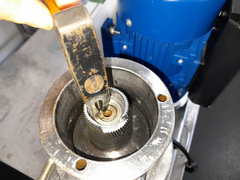
Rotate the seratted cone so that the keyways of the shaft and rotor align properly as shown above

Place the larger of the two key parts so that the top lip of the larger key gets to rest upon on the top surface of the shaft when pushed home within the shaft's keyway.

Only the larger key has been fitted in this photo

Follow through by placing the remaining smaller wedge shaped key sharp end first and to the outer part of the keyway to lock the shaft and rotor in place.
Gently tap home the top edge ot the keys to lock them into place with the small hammer.

The top of the shaft will ideally be around 1mm maximum below the bottom of the tapered edge of the rotors central hole.
If it is less than that, use the puller tool to withdraw the rotor from the housing and try again.

Another view of what the ideal depth of the shaft top edge relative to the rotor with the 20 mm o-ring in place in prepartion for the stainless steel panel washer to be placed upon it.

Stainless steel panel washer in place in preparation for auger placement

Get auger and turn nut on thread as shown in preparation for installation onto the grinder

Screw auger in (left hand thread) until firm the follow by tightening nut with spanner (left hand thread) until gently tight. DO NOT OVER TIGHTEN so as to push cone down the shaft. Use tools as shown to stablise movement when tightening.

what assembly should look like at this stage

Carefully place assembled waterjacket/alignment plate assembly vertically down into the appropriate alignement hole in the lower housing.
Keep things as vertically aligned as possible. Gently tap around the upper surface of the alighnment plate in an even manner to seat assembly into the lower housing.
Hint: Make sure the two holes into which the waterjacket hose couplings will be eventually screwed into, are facing towards the direction from which the water supply hoses will be coming from.

Assembly now fully tamped down into place

Take large white gasket ring and screw ring and assemble - see next 3 photos.


Ring now fully screwed down

select top plate, other large white o-ring and middle sized bolts and spring washers

Place o-ring and align top plate taking care to align all the holes correctly -
see next two photos as well.


NB: Back off the tighening ring a couple of turns from fully down position when complete.


Hand-tighen only the hose fittings. Rotate auger to allow installation of fittings.

Note how the edge of the hose fitting nut is aligned 'parralle' to the edge of the hole. This ensures easy fitment of the funnel later on.

find the remaining large o-ring and funnel and fit o-ring to it


Smear clear silicon grease to facilitate place of silicon gasket on discharge nozzel - see following slides as well.


Hint: Run hot water over end of large silicon product discharge pipe to aid its placement over the end of the square s/s product discharge nozzle.


placement of filtered water pipe